Page Summary
-
This guide is for SoC hardware designers integrating the Coral NPU into their system design as an AXI4/TileLink peripheral.
-
The SystemVerilog for the Coral NPU can be generated using specific Bazel build commands for scalar-only AXI or RISC-V vector AXI configurations.
-
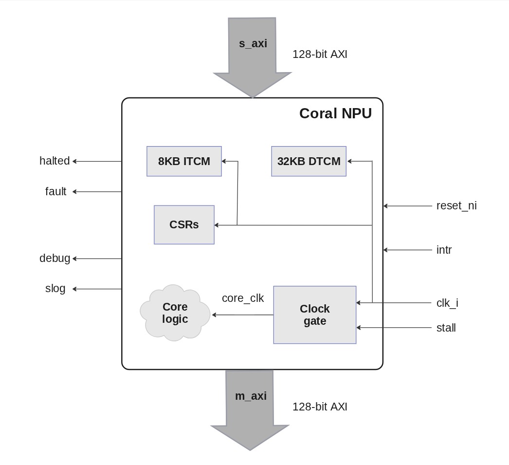
The Coral NPU interfaces primarily through an AXI4 slave and master, along with debug and status signals.
-
The memory map defines regions for ITCM (instruction memory), DTCM (data memory), and CSR (control/status registers) within the Coral NPU.
-
Booting the Coral NPU involves initializing instruction memory, programming the start PC, releasing the clock gate, and then releasing the reset, followed by monitoring status signals.
If you are an SoC hardware designer, follow the guidance here to generate the SystemVerilog for Coral NPU and to integrate it into your system design. The Coral NPU core will be an AXI4/TileLink peripheral in the system.
Generate SystemVerilog
A scalar-only Coral NPU configuration is provided that can integrate with an AXI-based system. The SystemVerilog can be generated with this build command:
bazel build //hdl/chisel/src/coralnpu:core_mini_axi_cc_library_emit_verilog
You can build the RISC-V vector (RV32IMF_Zve32x) version of Coral NPU with this command:
bazel build //hdl/chisel/src/coralnpu:rvv_core_mini_axi_cc_library_emit_verilog
Module interfaces
Notes:
- When
stallis asserted, the core logic is gated off (i.e.core_clk= 0). The S_AXI interface is still available to access ITCM and DTCM (tightly-couple memories) and CSRs (registers). - Before releasing
reset,stallshould be asserted to prevent Coral NPU from executing until the TCMs are initialized. Thenresetcan be released and the TCMs initialized. Then removestallto begin Coral NPU execution. haltedandfaultcan be used to set system CSRs and generate a system interrupt.
AXI bus
The interfaces to Coral NPU are as follows:
| Signal Bundle | Description |
|---|---|
| clk | The clock of the AXI bus / Coral NPU core. |
| reset | The active-low reset signal for the AXI bus/ Coral NPU core. |
| s_axi | An AXI4 slave interface that can be used to write TCMs or touch Coral NPU CSRs. |
| m_axi | An AXI4 master interface used by Coral NPU to read/write to memories/CSRs. |
| irqn | Active-low interrupt to the Coral NPU core. Can be triggered by peripherals or other host processor. |
| wfi | Active-high signal from the Coral NPU core, indicating that the core is waiting for an interrupt. While this is active, Coral NPU is clock-gated. |
| JTAG | IEEE 1149.1 JTAG Test Access Port (TAP) |
| halted | Output interface informing if the Coral NPU core is running or not. Can be ignored. |
| fault | Output interface to determine if the core hit a fault. These signals should be connected to a system control CPU interrupt-line or status register for notification when Coral NPU faults or is halted. |
AXI master signals
AR / AW channel
| Signal | Behavior |
|---|---|
| addr | Address Coral NPU wishes to read/write |
| prot | Always 2 (unprivileged, insecure, data) |
| id | Always 0 |
| len | (Count of beats in the burst) – 1 |
| size | Bytes-per-beat (1, 2, or 4) |
| burst | Always 1 (INCR) |
| lock | Always 0 (normal access) |
| cache | Always 0 (Device non-bufferable) |
| qos | Always 0 |
| region | Always 0 |
R channel
| Signal | Behavior |
|---|---|
| data | Response data from the slave |
| id | Ignored, but should be 0 as Coral NPU only emits txns with an id of 0 |
| resp | Response code |
| last | Whether the beat is the last in the burst |
W channel
| Signal | Behavior |
|---|---|
| data | Data Coral NPU wishes to write |
| last | Whether the beat is the last in the burst |
| strb | Which bytes in the data are valid |
B channel
| Signal | Behavior |
|---|---|
| id | Ignored, but should be 0 as Coral NPU only emits txns with an id of 0 (an RTL assertion exists for this) |
| resp | Response code |
AXI slave signals
AR / AW channel
| Signal | Behavior |
|---|---|
| addr | Address the master wishes to read / write to |
| prot | Ignored |
| id | Transaction ID, should be reflected in the response beats |
| len | (Count of beats in the burst) - 1 |
| size | Bytes-per-beat (1,2,4,8,16) |
| burst | 0, 1, or 2 (FIXED, INCR, WRAP) |
| lock | Ignored |
| cache | Ignored |
| qos | Ignored |
| region | Ignored |
R channel
| Signal | Behavior |
|---|---|
| data | Response data from Coral NPU |
| id | Transaction ID, should match with the id field from AR |
| resp | Response code (0/OKAY or 2/SLVERR) |
| last | Whether the beat is the last in the burst |
W channel
| Signal | Behavior |
|---|---|
| data | Data the master wishes to write to Coral NPU |
| last | Whether the beat is the last in the burst |
| strb | Which bytes in data is valid |
B channel
| Signal | Behavior |
|---|---|
| id | Transaction ID, should match with the id field from AW |
| resp | Response code (0/OKAY or 2/SLVERR) |
JTAG test and debug signals
| Signal | Behavior |
|---|---|
| TCK | Test Clock: clocks data and drives the internal TAP state machine. |
| TMS | Test Mode Select: sampled on the rising edge of TCK. |
| TDI | Test Data In: accepts serial instructions and data shifted into the device on the rising edge of TCK. |
| TDO | Test Data Out: outputs serial data from the internal registers on the falling edge of TCK. |
| TRST | Test Reset: optional active-low pin used to asynchronously reset the TAP state machine. |
Coral NPU memory map
Memory accesses to the Coral NPU are defined as follows:
| Region | Range | Size | Alignment | Description |
|---|---|---|---|---|
| ITCM | 0x0000 – 0x1FFF | 8 kB | 4 bytes | ITCM storage for code executed by Coral NPU. |
| DTCM | 0x10000 – 0x17FFF | 32 kB | 1 bytes | DTCM storage for data used by Coral NPU. |
| CSR | 0x30000 – TBD | TBD | 4 bytes | CSR interface used to query/control Coral NPU. |
Note that Coral NPU does not know its base address in the overall SoC system memory – that is determined by the SoC design. The SoC's host processor reads and writes to Coral's ITCM and DTCM SRAM memory, as well as to memory-mapped control/status registers in the CSR address range.
Reset considerations
Coral NPU uses a synchronous reset strategy. To ensure proper reset behavior, ensure that the clock runs for a cycle with reset active, before enabling either the internal clock gate (via CSR) or gating externally.
In the RISC-V architecture, Machine Mode (M-mode) is the most privileged execution level. It is primarily used for low-level hardware access, system initialization, and security management. A RISC-V processor always starts in M-mode upon power-up or reset.
M-mode has unrestricted access to all hardware resources, including all Control and Status Registers (CSRs) and physical memory. By default, M-mode operates directly on physical addresses without virtual memory translation.
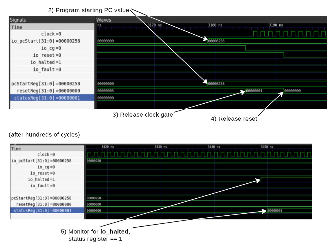
Booting Coral NPU
Note that in these examples, Coral NPU is located in the overall system memory map at address 0x0000 0000.
A timing diagram for this boot sequence is shown at the end of steps 1) – 5).
See Coral NPU custom CSRs for reference specifications for the register fields.
1) The instruction memory of Coral NPU must be initialized:
Sample code
volatile uint8_t* coralnpu_itcm = (uint8_t*)0x00000000L;
for (int i = 0; i < coralnpu_binary_len; ++i) {
   coralnpu_itcm[i] = coralnpu_binary[i];
}
or
Sample code
volatile uint8_t* coralnpu_itcm = (uint8_t*)0x00000000L;
memcpy(coralnpu_itcm, coralnpu_binary, coralnpu_binary_len);
If something like a DMA engine is present in your system, that is probably a
better option for initializing the ITCM.
2) Program the start PC value. If your program is linked such that the starting address is 0, you may skip this.
Sample code
volatile uint32_t* coralnpu_pc_csr = (uint32_t*)0x00030004L;
*coralnpu_pc_csr = start_addr;
3) Release clock gate
Sample code
volatile uint32_t* coralnpu_reset_csr = (uint32_t*)0x00030000L;
*coralnpu_reset_csr = 1;
After this, be sure to wait a cycle to allow Coral‘s reset to occur. If you want to configure something like an interrupt that is connected to Coral’s fault or halted outputs, this is a good time.
4) Release reset
Sample code
volatile uint32_t* coralnpu_reset_csr = (uint32_t*)0x00030000L;
*coralnpu_reset_csr = 0;
At this point, Coral NPU will begin executing at the PC value programmed in step 2.
5) Monitor for io_halted. The status of Coral's execution can be checked by
reading the status CSR:
Sample code
volatile uint32_t* coralnpu_status_csr = (uint32_t*)0x00030008L;
uint32_t status = *coralnpu_status_csr;
bool halted = status & 1;
bool fault = status & 2;