
When you specify altitude for features on a 3D map – such as lines, polygons, models, or markers – there are several factors that can affect their placement, both within the scene and in how the rendering of the scene interacts with that feature. This document covers the use of 'AltitudeMode' on a 3D map and how manage the altitude for features.
Here's how you can use AltitudeMode with a number of feature types:
Markers: Marker3DElement, Marker3DInteractiveElement
Specify an altitude on the location, and also extrusion.
Models: Model3DElement, Model3DInteractiveElement
Specify an altitude on the model's anchor point, which should be used with its orientation for proper positioning in the scene.
Polylines: Polyline3DElement, Polyline3DInteractiveElement
Specify how altitude is applied to position points along a polyline.
Polygons: Polygon3DElement, Polygon3DInteractiveElement
Specify how altitude is applied to position points along a polygon.
How Altitude is used in 3D Environments
When placing points within a 3D scene, their final position is influenced by the presence of captured 3D buildings or objects like trees. It's crucial to understand two key concepts:
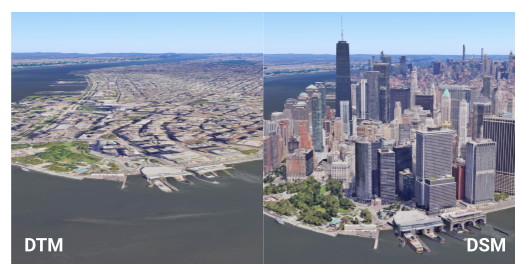
- Digital Terrain Model (DTM): This represents the "bare earth" elevation. Think of it as the natural shape of the land without any buildings, trees, or other structures on top. All areas are underpinned by the DTM, which forms the basis for the globe's elevation (calculated using EGM96).
- Digital Surface Model (DSM): This represents the "top surface" elevation, including buildings, trees, and other structures. In areas where features have been captured (particularly urban environments where buildings dominate the view), the visible surface will appear higher than the base terrain.
The distinction between DTM and DSM is vital for understanding how different altitude modes interact with these Digital Elevation Models (DEMs), as the placement of features might be obscured or influenced by the surface model. You can see the differences in the diagram below:
When Features Lack Altitude Data
If you have data which lacks an altitude measurement or when using data from
another Google service, such as the Routes or Places services, you often won't
have any altitude supplied in the returned geometry. In such cases, placing the
feature in the scene requires you to choose an AltitudeMode carefully:
- Clamp it to the ground: The simplest approach, where the feature will automatically conform to the terrain. This mode uses the DTM model.
- Give it an arbitrary altitude + relative mode: You can assign a chosen altitude and then use RELATIVE_TO_GROUND (which places features relative to the DTM model) or RELATIVE_TO_MESH (which floats them above the DSM model).
- Use another service to obtain altitude: For precise DTM altitude at the feature's location, you can use a service like the Google Maps Platform Elevation API. If it's a line or polygon, you'll need to do this for each of the points that make up the line or polygon.
What AltitudeMode options mean and when to use them?
There are four AltitudeMode options you can specify when defining a feature:
ABSOLUTE
Imagine an airplane flying at a specific altitude above sea level, say 10,000 feet. Its height is fixed, no matter if it's flying over a mountain or a valley.
How to use it: Object altitude is expressed relative to the average mean sea level (calculated using EGM96). The feature's altitude coordinate is interpreted as a precise elevation above mean sea level.
When to use it: For features with known, precise altitudes, such as flight paths, submerged objects with exact depth, or fixed-point scientific instruments.
CLAMP_TO_GROUND
Think of placing a picnic blanket directly on a hillside. No matter how steep or flat the hill is, the blanket always lies flat on the visible surface.
How to use it: Object altitude is expressed as placed directly on the ground. They will remain at ground level, following the terrain, regardless of any altitude value provided. The feature's altitude coordinate is ignored; it's projected directly onto the terrain surface (DTM).
When to use it: For features that should always conform to the terrain, like roads, fences, trails, property boundaries, or the base of buildings.
RELATIVE_TO_GROUND
Picture a hot air balloon that stays 100 meters above whatever the natural ground elevation (DTM) is beneath it. If the ground goes up, the balloon goes up with it, maintaining that 100-meter gap from the "bare earth."
How to use it: Object altitude is expressed relative to the ground surface (DTM). The feature's altitude coordinate is interpreted as an offset from the terrain elevation at its horizontal position.
When to use it: For objects that need to maintain a consistent height above the natural terrain, such as communication towers or overhead lines in rural areas.
RELATIVE_TO_MESH
This is like a drone flying a fixed height above whatever it's flying over, whether that's the bare ground, a building roof, or the top of a tree. It adjusts to the highest visible surface (DSM).
How to use it: Object altitude is expressed relative to the highest of the ground+building+water surface (DSM). The feature's altitude coordinate is interpreted as an offset from the DSM elevation.
When to use it: For objects that need to float a certain height above whatever is physically there (DTM, buildings, water), useful for markers on roofs or features that dynamically adjust to the visible scene.
For more details, see the documentation for the AltitudeMode constants.
Visual examples and practical applications
These examples use a specific location, Stonehenge, to illustrate how different
AltitudeMode options affect feature placement. These examples first cover
positioning markers, then lines and areas, which have a few different
considerations.
Position Markers
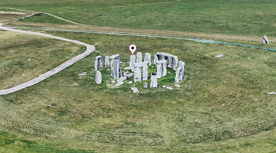
Consider a pin marker placed as follows:
const markerLocation = { lat: 51.1789, lng: -1.8262, altitude: 102.23 };
You can see this as the white pin in the scene below:
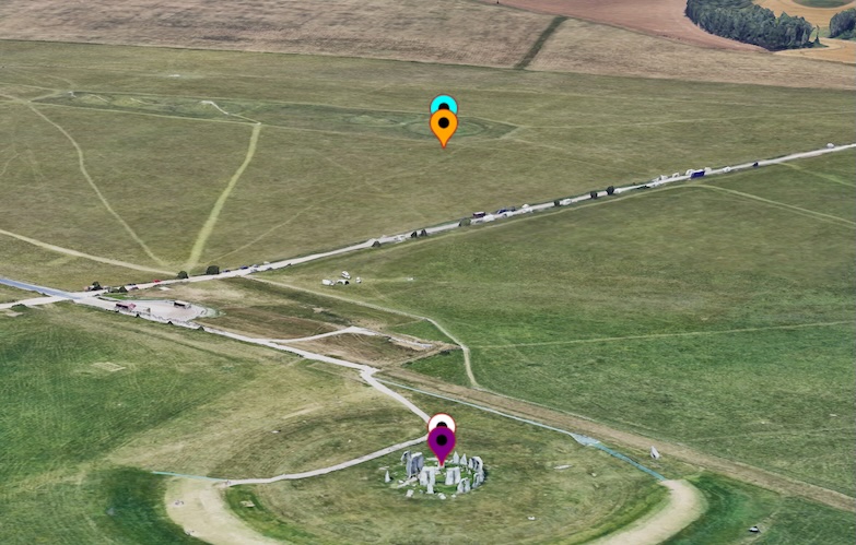
Now look at the image below which shows pins of various colors positioned using the different altitude modes.
Let us take a look at how the different AltitudeModeaffects the positioning of
the marker in ascending order of elevation.
CLAMP_TO_GROUND (Purple Pin)
This pin ignores the altitude value and attaches itself to the nearest ground elevation. You can see it just below the white pin, effectively "clamping" to the terrain.
Technically, this mode ignores the actual altitude and clamps the pin to the nearest DTM height.
ABSOLUTE (White Pin)
This pin uses the exact altitude value (102.23m) to place the marker at that height above sea level (EGM96), appearing on top of one of the Stonehenge stones as specified by its supplied altitude.
Technically, this mode uses the actual supplied altitude value to place the pin at the specified height above sea level, which in this example is the location of Stonehenge, but at the top of one of the stones.
RELATIVE_TO_GROUND (Orange Pin)
This pin takes the ground (DTM) as its base and places itself 102.23m above that ground level, appearing to float above the natural ground that is under the stone in the henge.
Technically, this mode sets its base to the level of the actual DTM on the ground and then places the pin at 102.23m above it.
RELATIVE_TO_MESH (Blue Pin)
This pin uses the visible surface (DSM) as its base and places itself 102.23m above that surface. This mode includes the stone's height in its measurement, aligning it slightly higher than the orange pin.
Technically, this mode uses the mesh (DSM) as the base and places the location at the given altitude above that. Since the DSM is at the top of the standing stone, this pin includes this extra height in its measurement when determining its relative height, aligning it slightly higher than the RELATIVE_TO_GROUND pin.
Position Lines and Areas
For lines and areas, both the altitude of the points within the feature (whether
specified or not) and the AltitudeMode being used are crucial. Let us
examine a line along Stonehenge with the following specified altitudes:
const lineCoords = [
   { lat: 51.1786, lng : -1.8266, altitude: 101.36 },
   { lat: 51.1787, lng : -1.8264, altitude: 101.18 },
   { lat: 51.178778, lng : -1.826354, altitude: 104.89 },
   { lat: 51.178815, lng : -1.826275, altitude: 107.55 },
   { lat: 51.178923, lng : -1.825980, altitude: 105.53 },
   { lat: 51.1791, lng : -1.8258, altitude: 100.29 },
   { lat: 51.1792, lng : -1.8257, altitude: 100.29 }
];
You can see this line represented in the image below in white, using absolute positioning.

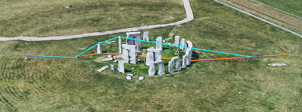
Once again, the image below shows the lines using different altitude modes. Let us discuss each in turn, from lowest to highest.
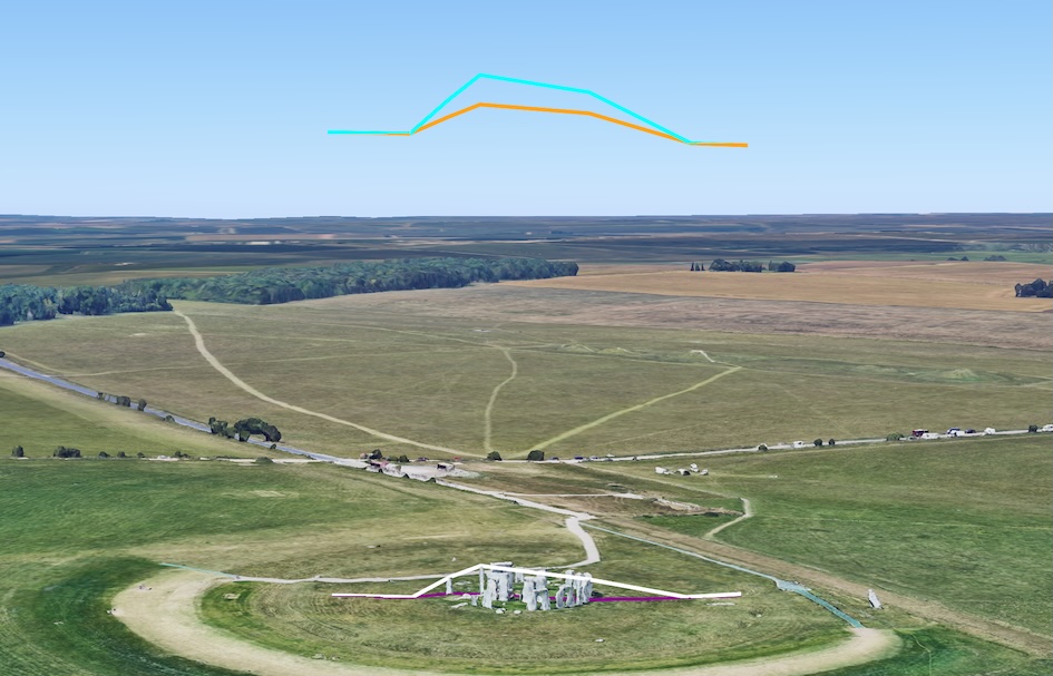
CLAMP_TO_GROUND (Purple Line)
This line ignores the specified altitude for each point and instead "drapes" the line directly over the underlying ground (DTM). It follows the terrain, ignoring the presence of any features like buildings or stones above it.
Technically, this mode ignores the actual altitude values and drapes the line over the DTM, following the underlying terrain and ignoring the mesh of features above it.
ABSOLUTE (White Line)
This line uses the exact altitude for each point, causing the line to go over some of the stones. It is connected by straight lines between each point, which can sometimes make it appear to pass through objects if the points are not frequent enough.
Technically, this mode follows the specified altitude for each point, connecting them with straight lines, meaning it can pass through the mesh (for example: stones) if the altitude values dictate. This scenario is covered in a later section.
RELATIVE_TO_GROUND (Orange Line)
This line uses the natural ground (DTM) as its base and places each point at the specified altitude above that ground level.
Technically, this mode uses the DTM as the base and places the line locations at the listed altitude relative to it.
RELATIVE_TO_MESH (Blue Line)
This line uses the visible surface, which includes buildings and stones, as its base. It then places each point at the specified altitude above that mesh, effectively replicating the line's shape in relation to the visible landscape.
Technically, this mode uses the mesh (DSM) as the base and places the locations at the specified altitude above that, depending on the mesh the line might alter given the different features on the ground.
When Altitude is Not Specified for Lines
Now, let us consider the same line coordinates but without any altitude specified:
const lineCoords = [
   { lat: 51.1786, lng : -1.8266 },
   { lat: 51.1787, lng : -1.8264 },
   { lat: 51.178778, lng : -1.826354 },
   { lat: 51.178815, lng : -1.826275 },
   { lat: 51.178923, lng : -1.825980 },
   { lat: 51.1791, lng : -1.8258 },
   { lat: 51.1792, lng : -1.8257 }
];
In this scenario, where no altitude is provided, the lines often appear in similar locations. The White, orange, and purple lines might merge into a single line (orange, as it's typically drawn last) because they all default to a similar ground-level positioning. You can see this below:
The blue line (RELATIVE_TO_MESH) again uses the mesh (DSM) as the base. Since no altitude is specified, it just overlays the points directly on top of the mesh. It's important to note that it doesn't lay the line on the mesh but connects the specified points on the mesh with straight connections. While this might look acceptable in some examples, it can cause visibility issues when covered by other features. This issue is covered in the next section.
The interaction of meshes and lines. Now we can look at another polyline. This image is in the same area but with more ground coverage (or more detail on the DSM on top of the DTM).
const lineCoords = [
    { lat: 51.188404, lng: -1.779059, altitude: 70.69 },
    { lat: 51.187955, lng: -1.780143, altitude: 77.25 },
    { lat: 51.187658, lng: -1.781552, altitude: 68.97 },
    { lat: 51.187376, lng: -1.782447, altitude: 99.02 },
    { lat: 51.186912, lng: -1.783692, altitude: 104.35 },
    { lat: 51.185855, lng: -1.788368, altitude: 86.91 },
];
When we see the representation using the same methods (and colors) of before, we get this view:
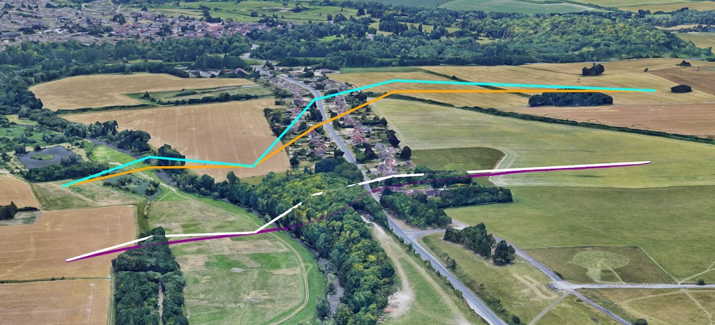
Purple is CLAMP_TO_GROUND, which you can see going along the ground. White is ABSOLUTE, which you can see that straight lines connect the points which are positioned absolutely in space. With orange and blue being relative versions either about the SURFACE (DTM) or MESH (DSM), note the blue line is slightly different in form due to the height of the features below.
Again we can note the nature of the line creation means that the line passes through the mesh as the points are connected together by straight lines. This scenario might cause issues in seeing the lines, so you can set drawsOccludedSegments to true to make sure the line is visible through the trees, as shown in more detail in the following image, where the lines passing through the mesh can still be seen.
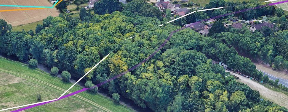
The nature of positioning in space means that the points might fall within the mesh and also the lines connecting the points might also fall into the mesh, potentially causing visual artifacts. In the section below we may see how such artifacts might be improved where possible.
Solving issues in the interaction between lines and terrain
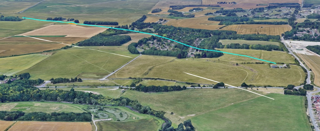
In another example, in the same area, we can see some other artifacts that we must be aware of when using specific altitude modes.
Here we have a relatively flat area which is mainly at the level of the DTM, with limited extra details above it in the mesh. This scenario would also be the case in an area which had no 3d coverage above the terrain model. Let us take a look at the following location, as specified below:
const lineCoords = [
   { lat: 51.194642, lng: -1.782636, altitude: 99.10 },
   { lat: 51.193974, lng: -1.783952, altitude: 99.86 },
   { lat: 51.192203, lng: -1.787175, altitude: 96.14 },
   { lat: 51.190024, lng: -1.790250, altitude: 105.92 },
   { lat: 51.187491, lng: -1.793580, altitude: 102.60 },
   { lat: 51.183690, lng: -1.798745, altitude: 95.69 },
];
And can seen in the image, with the lines having the same color representation as before: (white : ABSOLUTE, blue : RELATIVE_TO_MESH, purple : CLAMP_TO_GROUND, orange : RELATIVE_TO_GROUND).

Here we can see a number of artifacts, the first of which is that due to the lack of surface cover the orange (RELATIVE_TO_GROUND) and blue (RELATIVE_TO_MESH) lines are in (mostly) the same location (with the blue line being shown as it is drawn last).
We can also see that the purple (CLAMP_TO_GROUND) line follows the ground and can be seen on the hill, whilst the white (ABSOLUTE) line can be seen as disappearing into the hill as only the points are connected and the straight lines go through the ground.
You can see this specifically in this image when the purple line has been hidden.
This can therefore lead to some strange visual artifacts, where the line can be seen to disappear under the ground (or even through the mesh) as the line between the points just follows a straight path. You might be able to improve the visual display of such a line by adding more points between the lines through using an interpolation method, how this might affect the visual will once again be dependent on the method being used:
- For Relative Measurements (RELATIVE_TO_GROUND or RELATIVE_TO_MESH): When using relative altitude values, creating more points along a line or polygon will allow the feature to be placed at a more appropriate level, conforming better to the elevation profile. If these intermediary points aren't present in your data, you can use an interpolation function, such as the Interpolate function in the Google Maps Platform Geometry library, to add them. These new points can then be given relative values that will be placed above the relevant elevation profile and then the length of any line joining the points will be limited and visual representation improved.
- For Absolute Features (ABSOLUTE): For ABSOLUTE features, more points will need to have actual altitude values. Interpolating between existing absolute values won't give a point that accurately reflects any value above the mesh, as it would merely be an average between point A and point B.
Summary
Hopefully this document has provided you a comprehensive overview of
AltitudeMode options in Photorealistic 3D Maps, detailing how ABSOLUTE,
CLAMP_TO_GROUND, RELATIVE_TO_GROUND, and RELATIVE_TO_MESH impact the placement
and rendering of various features like markers, lines, and polygons.
Understanding how these modes work together with the underlying Digital Terrain Model (DTM) and Digital Surface Model (DSM) is crucial to create accurate and visually compelling 3D map representations with the minimum of visual artifacts.
We hope you will experiment with these altitude modes in your own projects to unlock the full potential of 3D mapping and create engaging, immersive experiences for your users and provide feedback.
Contributors
Matt Toon | Solutions Engineer, Geo Developer