- Dataset-Verfügbarkeit
- 2021-10-28T23:17:26Z–2026-07-10T14:47:38.357000Z
- Ersteller des Datasets
- USGS
- Wiederholungsintervall
- 16 Tage
- Tags
Beschreibung
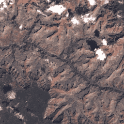
Landsat 8 Collection 2 Tier 2-DN-Werte, die die skalierten, kalibrierten Sensormesswerte darstellen. Szenen, die die Kriterien für Stufe 1 während der Verarbeitung nicht erfüllen, werden Stufe 2 zugewiesen. Dazu gehören systematisch verarbeitete Szenen (L1GT und L1GS) sowie alle L1TP-Szenen, die aufgrund von starker Wolkenbedeckung, unzureichender Bodenkontrolle und anderen Faktoren nicht den Tier 1-Spezifikationen entsprechen. Nutzer, die sich für Szenen der Stufe 2 interessieren, können den RMSE und andere Eigenschaften analysieren, um die Eignung für die Verwendung in einzelnen Anwendungen und Studien zu ermitteln. Weitere Informationen finden Sie in der USGS-Dokumentation.
Bänder
Bänder
Pixelgröße: variiert
| Name | Pixelgröße | Wellenlänge | Beschreibung | ||||||||||||||||||||||||||||||||||||||||||||||||||||||||||||||||||||||||||||||||||||||||||||||||
|---|---|---|---|---|---|---|---|---|---|---|---|---|---|---|---|---|---|---|---|---|---|---|---|---|---|---|---|---|---|---|---|---|---|---|---|---|---|---|---|---|---|---|---|---|---|---|---|---|---|---|---|---|---|---|---|---|---|---|---|---|---|---|---|---|---|---|---|---|---|---|---|---|---|---|---|---|---|---|---|---|---|---|---|---|---|---|---|---|---|---|---|---|---|---|---|---|---|---|---|
B1 |
30 Meter | 0,43–0,45 μm | Küstenaerosol |
||||||||||||||||||||||||||||||||||||||||||||||||||||||||||||||||||||||||||||||||||||||||||||||||
B2 |
30 Meter | 0,45–0,51 μm | Blau |
||||||||||||||||||||||||||||||||||||||||||||||||||||||||||||||||||||||||||||||||||||||||||||||||
B3 |
30 Meter | 0,53–0,59 μm | Grün |
||||||||||||||||||||||||||||||||||||||||||||||||||||||||||||||||||||||||||||||||||||||||||||||||
B4 |
30 Meter | 0,64–0,67 μm | Rot |
||||||||||||||||||||||||||||||||||||||||||||||||||||||||||||||||||||||||||||||||||||||||||||||||
B5 |
30 Meter | 0,85–0,88 μm | Nahes Infrarot |
||||||||||||||||||||||||||||||||||||||||||||||||||||||||||||||||||||||||||||||||||||||||||||||||
B6 |
30 Meter | 1,57–1,65 μm | Kurzwellen-Infrarot 1 |
||||||||||||||||||||||||||||||||||||||||||||||||||||||||||||||||||||||||||||||||||||||||||||||||
B7 |
30 Meter | 2,11–2,29 μm | Kurzwellen-Infrarot 2 |
||||||||||||||||||||||||||||||||||||||||||||||||||||||||||||||||||||||||||||||||||||||||||||||||
B8 |
15 Meter | 0,52–0,90 μm | Band 8 (panchromatisch) |
||||||||||||||||||||||||||||||||||||||||||||||||||||||||||||||||||||||||||||||||||||||||||||||||
B9 |
30 Meter | 1,36–1,38 μm | Zirrus |
||||||||||||||||||||||||||||||||||||||||||||||||||||||||||||||||||||||||||||||||||||||||||||||||
B10 |
30 Meter | 10,60–11,19 μm | Thermales Infrarot 1, von 100 m auf 30 m neu berechnet |
||||||||||||||||||||||||||||||||||||||||||||||||||||||||||||||||||||||||||||||||||||||||||||||||
B11 |
30 Meter | 11,50–12,51 μm | Thermales Infrarot 2, von 100 m auf 30 m neu berechnet |
||||||||||||||||||||||||||||||||||||||||||||||||||||||||||||||||||||||||||||||||||||||||||||||||
QA_PIXEL |
30 Meter | Keine | Landsat Collection 2 OLI/TIRS QA Bitmask |
||||||||||||||||||||||||||||||||||||||||||||||||||||||||||||||||||||||||||||||||||||||||||||||||
QA_RADSAT |
30 Meter | Keine | QA für radiometrische Sättigung |
||||||||||||||||||||||||||||||||||||||||||||||||||||||||||||||||||||||||||||||||||||||||||||||||
SAA |
30 Meter | Keine | Solar-Azimutwinkel |
||||||||||||||||||||||||||||||||||||||||||||||||||||||||||||||||||||||||||||||||||||||||||||||||
SZA |
30 Meter | Keine | Sonnen-Zenitwinkel |
||||||||||||||||||||||||||||||||||||||||||||||||||||||||||||||||||||||||||||||||||||||||||||||||
VAA |
30 Meter | Keine | Aufnahme-Azimutwinkel |
||||||||||||||||||||||||||||||||||||||||||||||||||||||||||||||||||||||||||||||||||||||||||||||||
VZA |
30 Meter | Keine | Aufnahme-Zenitwinkel |
||||||||||||||||||||||||||||||||||||||||||||||||||||||||||||||||||||||||||||||||||||||||||||||||
Bildattribute
Bildeigenschaften
| Name | Typ | Beschreibung |
|---|---|---|
| CLOUD_COVER | DOUBLE | Prozentsatz der Wolkendecke (0–100), -1 = nicht berechnet. |
| CLOUD_COVER_LAND | DOUBLE | Prozentsatz der Wolkendecke über Land (0–100), -1 = nicht berechnet. |
| COLLECTION_CATEGORY | STRING | Tier der Szene. (T1 oder T2) |
| COLLECTION_NUMBER | DOUBLE | Nummer der Sammlung. |
| DATA_SOURCE_ELEVATION | STRING | Gibt die Quelle des im Korrekturprozess verwendeten DEM an. Mögliche Werte: „GLS2000“, „RAMP“, „GTOPO30“.' |
| DATA_SOURCE_TIRS_STRAY_LIGHT_CORRECTION | STRING | Die Korrekturquelle, die zum Erstellen des Korrekturbilds für Streulicht des Landsat 8 TIRS verwendet wurde. Dieses Feld ist für Landsat 9 nicht enthalten. |
| DATE_ACQUIRED | STRING | Aufnahmedatum des Bildes. „JJJJ-MM-TT“ |
| DATE_PRODUCT_GENERATED | INT | Epoche der Produktgenerierung. |
| DATUM | STRING | Das Datum, das bei der Bilderstellung verwendet wurde. |
| EARTH_SUN_DISTANCE | DOUBLE | Entfernung zwischen Erde und Sonne in astronomischen Einheiten (AE). |
| ELLIPSOID | STRING | Das Ellipsoid, das bei der Bilderstellung verwendet wurde. |
| GEOMETRIC_RMSE_MODEL | DOUBLE | Kombinierte Wurzel der mittleren Fehlerquadratsumme (RMSE) der geometrischen Residuen (Meter) sowohl in Quer- als auch in Längsrichtung, gemessen an den GCPs, die für die Korrektur der geometrischen Präzision verwendet wurden. Nicht in L1G-Produkten vorhanden. |
| GEOMETRIC_RMSE_MODEL_X | DOUBLE | RMSE der geometrischen Residuen in X-Richtung (in Metern), gemessen an den GCPs, die für die Korrektur der geometrischen Genauigkeit verwendet wurden. Nicht in L1G-Produkten vorhanden. |
| GEOMETRIC_RMSE_MODEL_Y | DOUBLE | RMSE der geometrischen Residuen in Y-Richtung (in Metern), gemessen an den GCPs, die für die Korrektur der geometrischen Genauigkeit verwendet wurden. Nicht in L1G-Produkten vorhanden. |
| GRID_CELL_SIZE_PANCHROMATIC | DOUBLE | Die Größe der Rasterzelle, die beim Erstellen des Bildes für das panchromatische Band verwendet wurde. |
| GRID_CELL_SIZE_REFLECTIVE | DOUBLE | Die Größe der Rasterzelle, die beim Erstellen des Bildes für das reflektierende Band verwendet wurde. |
| GRID_CELL_SIZE_THERMAL | DOUBLE | Die Größe der Rasterzelle, die beim Erstellen des Bildes für das thermische Band verwendet wurde. |
| GROUND_CONTROL_POINTS_MODEL | DOUBLE | Die Anzahl der verwendeten Bodenkontrollpunkte. Wird in L1GT-Produkten nicht verwendet. Werte: 0–999 (0 wird für L1T-Produkte verwendet, bei denen die Funktion „Multi-Scene Refinement“ genutzt wurde). |
| GROUND_CONTROL_POINTS_VERSION | DOUBLE | Die Anzahl der Bodenkontrollpunkte, die bei der Überprüfung des geländekorrigierten Produkts verwendet wurden. Werte: -1 bis 1615 (-1 = nicht verfügbar) |
| IMAGE_QUALITY_OLI | DOUBLE | Die zusammengesetzte Bildqualität für die OLI-Bänder. Werte: 9 = Beste. 1 = Schlechteste. 0 = Die Bildqualität wurde nicht berechnet. Dieser Parameter ist nur vorhanden, wenn OLI-Bänder im Produkt enthalten sind. |
| IMAGE_QUALITY_TIRS | DOUBLE | Die zusammengesetzte Bildqualität für die TIRS-Bänder. Werte: 9 = Beste. 1 = Schlechteste. 0 = Die Bildqualität wurde nicht berechnet. Dieser Parameter ist nur vorhanden, wenn OLI-Bänder im Produkt enthalten sind. |
| K1_CONSTANT_BAND_10 | DOUBLE | K1-Kalibrierungskonstante für die Umrechnung der Strahlung von Band 10 in Temperatur. |
| K1_CONSTANT_BAND_11 | DOUBLE | K1-Kalibrierungskonstante für die Umrechnung der Strahlung von Band 11 in Temperatur. |
| K2_CONSTANT_BAND_10 | DOUBLE | K2-Kalibrierungskonstante für die Umrechnung der Strahlung von Band 10 in Temperatur. |
| K2_CONSTANT_BAND_11 | DOUBLE | K2-Kalibrierungskonstante für die Umrechnung der Strahlung von Band 11 in Temperatur. |
| LANDSAT_PRODUCT_ID | STRING | Die Namenskonvention für jedes Landsat Collection N Level-1-Bild basiert auf Erfassungs- und Verarbeitungsparametern. Format: LXSS_LLLL_PPPRRR_YYYYMMDD_yyyymmdd_CC_TX
|
| LANDSAT_SCENE_ID | STRING | Die Namenskonvention für jedes Bild vor der Erfassung basiert auf den Erfassungsparametern. Dies war die Namenskonvention, die vor Collection 1 verwendet wurde. Format: LXSPPPRRRYYYYDDDGSIVV
|
| MAP_PROJECTION | STRING | Projektion, die zur Darstellung der dreidimensionalen Erdoberfläche für das Produkt der Stufe 1 verwendet wird. |
| NADIR_OFFNADIR | STRING | Nadir- oder Off-Nadir-Bedingung der Szene. |
| ORIENTATION | STRING | Die Ausrichtung, die beim Erstellen des Bildes verwendet wurde. Werte: NOMINAL = Nominal Path (Nomineller Pfad), NORTH_UP = North Up (Norden oben), TRUE_NORTH = True North (Tatsächlicher Norden), USER = User (Nutzer) |
| PANCHROMATIC_LINES | DOUBLE | Anzahl der Produktlinien für das panchromatische Band. |
| PANCHROMATIC_SAMPLES | DOUBLE | Anzahl der Produktstichproben für die panchromatischen Bänder. |
| PROCESSING_SOFTWARE_VERSION | STRING | Name und Version der Verarbeitungssoftware, die zum Generieren des L1-Produkts verwendet wurde. |
| RADIANCE_ADD_BAND_1 | DOUBLE | Additiver Reskalierungsfaktor, der verwendet wird, um kalibrierte DN für Band 1 in Strahlung umzuwandeln. |
| RADIANCE_ADD_BAND_10 | DOUBLE | Additiver Reskalierungsfaktor, der verwendet wird, um kalibrierte DN für Band 10 in Strahlung umzuwandeln. |
| RADIANCE_ADD_BAND_11 | DOUBLE | Additiver Reskalierungsfaktor, der verwendet wird, um kalibrierte DN für Band 11 in Strahlung umzuwandeln. |
| RADIANCE_ADD_BAND_2 | DOUBLE | Additiver Reskalierungsfaktor, der verwendet wird, um kalibrierte DN für Band 2 in Strahlung umzuwandeln. |
| RADIANCE_ADD_BAND_3 | DOUBLE | Additiver Reskalierungsfaktor, der verwendet wird, um kalibrierte DN für Band 3 in Strahlung umzuwandeln. |
| RADIANCE_ADD_BAND_4 | DOUBLE | Additiver Reskalierungsfaktor, der verwendet wird, um kalibrierte DN für Band 4 in Strahlung umzuwandeln. |
| RADIANCE_ADD_BAND_5 | DOUBLE | Additiver Reskalierungsfaktor, der verwendet wird, um kalibrierte DN für Band 5 in Strahlung umzuwandeln. |
| RADIANCE_ADD_BAND_6 | DOUBLE | Additiver Reskalierungsfaktor, der verwendet wird, um kalibrierte DN für Band 6 in Strahlung umzuwandeln. |
| RADIANCE_ADD_BAND_7 | DOUBLE | Additiver Reskalierungsfaktor, der verwendet wird, um kalibrierte DN für Band 7 in Strahlung umzuwandeln. |
| RADIANCE_ADD_BAND_8 | DOUBLE | Additiver Reskalierungsfaktor, der verwendet wird, um kalibrierte DN für Band 8 in Strahlung umzuwandeln. |
| RADIANCE_ADD_BAND_9 | DOUBLE | Additiver Reskalierungsfaktor, der verwendet wird, um kalibrierte DN für Band 9 in Strahlung umzuwandeln. |
| RADIANCE_MULT_BAND_1 | DOUBLE | Multiplikativer Skalierungsfaktor, der verwendet wird, um kalibrierte DN von Band 1 in Strahlung umzuwandeln. |
| RADIANCE_MULT_BAND_10 | DOUBLE | Multiplikativer Skalierungsfaktor, der verwendet wird, um kalibrierte DN von Band 10 in Strahlung umzuwandeln. |
| RADIANCE_MULT_BAND_11 | DOUBLE | Multiplikativer Skalierungsfaktor, der verwendet wird, um kalibrierte DN von Band 11 in Strahlung umzuwandeln. |
| RADIANCE_MULT_BAND_2 | DOUBLE | Multiplikativer Skalierungsfaktor, der verwendet wird, um kalibrierte DN für Band 2 in Strahlung umzuwandeln. |
| RADIANCE_MULT_BAND_3 | DOUBLE | Multiplikativer Skalierungsfaktor, der verwendet wird, um kalibrierte DN für Band 3 in Strahlung umzuwandeln. |
| RADIANCE_MULT_BAND_4 | DOUBLE | Multiplikativer Reskalierungsfaktor, der verwendet wird, um kalibrierte DN für Band 4 in Strahlung umzuwandeln. |
| RADIANCE_MULT_BAND_5 | DOUBLE | Multiplikativer Reskalierungsfaktor, der verwendet wird, um kalibrierte DN für Band 5 in Strahlung umzuwandeln. |
| RADIANCE_MULT_BAND_6 | DOUBLE | Multiplikativer Reskalierungsfaktor, der verwendet wird, um kalibrierte DN für Band 6 in Strahlung umzuwandeln. |
| RADIANCE_MULT_BAND_7 | DOUBLE | Multiplikativer Skalierungsfaktor, der verwendet wird, um kalibrierte DN für Band 7 in Strahlung umzuwandeln. |
| RADIANCE_MULT_BAND_8 | DOUBLE | Multiplikativer Skalierungsfaktor, der verwendet wird, um kalibrierte DN für Band 8 in Strahlung umzuwandeln. |
| RADIANCE_MULT_BAND_9 | DOUBLE | Multiplikativer Skalierungsfaktor, der verwendet wird, um kalibrierte DN von Band 9 in Strahlung umzuwandeln. |
| REFLECTANCE_ADD_BAND_1 | DOUBLE | Additiver Reskalierungsfaktor, der zum Konvertieren der kalibrierten DN von Band 1 in Reflexionsvermögen verwendet wird. |
| REFLECTANCE_ADD_BAND_2 | DOUBLE | Additiver Reskalierungsfaktor, der verwendet wird, um kalibrierte DN für Band 2 in Reflexionsvermögen umzuwandeln. |
| REFLECTANCE_ADD_BAND_3 | DOUBLE | Additiver Reskalierungsfaktor, der zum Konvertieren kalibrierter DN für Band 3 in Reflexionsvermögen verwendet wird. |
| REFLECTANCE_ADD_BAND_4 | DOUBLE | Additiver Reskalierungsfaktor, der verwendet wird, um kalibrierte DN für Band 4 in Reflexionsvermögen umzuwandeln. |
| REFLECTANCE_ADD_BAND_5 | DOUBLE | Additiver Reskalierungsfaktor, der verwendet wird, um kalibrierte DN für Band 5 in Reflexionsvermögen umzuwandeln. |
| REFLECTANCE_ADD_BAND_7 | DOUBLE | Multiplikativer Faktor, der verwendet wird, um kalibrierte DN für Band 7 in Reflexionsvermögen umzuwandeln. |
| REFLECTANCE_ADD_BAND_8 | DOUBLE | Multiplikativer Faktor, der zum Konvertieren der kalibrierten DN von Band 8 in Reflexionsvermögen verwendet wird. |
| REFLECTANCE_ADD_BAND_9 | DOUBLE | Der niedrigste erreichbare spektrale Reflexionswert für Band 8. |
| REFLECTANCE_MULT_BAND_1 | DOUBLE | Multiplikativer Faktor, der zum Konvertieren der kalibrierten DN von Band 1 in die Reflektanz verwendet wird. |
| REFLECTANCE_MULT_BAND_2 | DOUBLE | Multiplikativer Faktor, der zum Konvertieren der kalibrierten DN von Band 2 in Reflexionsvermögen verwendet wird. |
| REFLECTANCE_MULT_BAND_3 | DOUBLE | Multiplikativer Faktor, der verwendet wird, um kalibrierte DN von Band 3 in Reflexionsvermögen umzuwandeln. |
| REFLECTANCE_MULT_BAND_4 | DOUBLE | Multiplikativer Faktor, der verwendet wird, um kalibrierte DN für Band 4 in Reflexionsvermögen umzuwandeln. |
| REFLECTANCE_MULT_BAND_5 | DOUBLE | Multiplikativer Faktor, der zum Konvertieren von kalibrierten DN für Band 5 in Reflexionsvermögen verwendet wird. |
| REFLECTANCE_MULT_BAND_6 | DOUBLE | Multiplikativer Faktor, der verwendet wird, um kalibrierte DN für Band 6 in Reflexionsvermögen umzuwandeln. |
| REFLECTANCE_MULT_BAND_7 | DOUBLE | Multiplikativer Faktor, der verwendet wird, um kalibrierte DN für Band 7 in Reflexionsvermögen umzuwandeln. |
| REFLECTANCE_MULT_BAND_8 | DOUBLE | Multiplikativer Faktor, der zum Konvertieren der kalibrierten DN von Band 8 in Reflexionsvermögen verwendet wird. |
| REFLECTANCE_MULT_BAND_9 | DOUBLE | Multiplikativer Faktor, der zum Konvertieren kalibrierter DN von Band 9 in Reflexionsvermögen verwendet wird. |
| REFLECTIVE_LINES | DOUBLE | Anzahl der Produktlinien für die reflektierenden Bänder. |
| REFLECTIVE_SAMPLES | DOUBLE | Anzahl der Produktmuster für die reflektierenden Bänder. |
| REQUEST_ID | STRING | Anfrage-ID, nnnyymmdd0000_0000
|
| RESAMPLING_OPTION | STRING | Die Resampling-Option, die beim Erstellen des Bildes verwendet wurde. |
| ROLL_ANGLE | DOUBLE | Der Rollwinkel des Raumfahrzeugs im Zentrum der Szene. |
| SATURATION_BAND_1 | STRING | Flag für gesättigte Pixel für Band 1 („Y“/„N“) |
| SATURATION_BAND_10 | STRING | Flag für gesättigte Pixel für Band 10 („Y“/„N“) |
| SATURATION_BAND_11 | STRING | Flag, das gesättigte Pixel für Band 11 angibt („Y“/„N“) |
| SATURATION_BAND_2 | STRING | Flag für gesättigte Pixel für Band 2 („Y“/„N“) |
| SATURATION_BAND_3 | STRING | Flag für gesättigte Pixel für Band 3 („Y“/„N“) |
| SATURATION_BAND_4 | STRING | Flag für gesättigte Pixel für Band 4 („Y“/„N“) |
| SATURATION_BAND_5 | STRING | Flag für gesättigte Pixel für Band 5 („Y“/„N“) |
| SATURATION_BAND_6 | STRING | Flag, das gesättigte Pixel für Band 6 angibt („Y“/„N“) |
| SATURATION_BAND_7 | STRING | Flag für gesättigte Pixel für Band 7 („Y“/„N“) |
| SATURATION_BAND_8 | STRING | Flag für gesättigte Pixel für Band 8 („Y“/„N“) |
| SATURATION_BAND_9 | STRING | Flag, das gesättigte Pixel für Band 9 angibt („Y“/„N“) |
| SCENE_CENTER_TIME | STRING | Zeitpunkt des Bildzentrums des aufgenommenen Bildes. HH:MM:SS.SSSSSSSZ
|
| SENSOR_ID | STRING | Sensor, der zum Erfassen von Daten verwendet wird. |
| SPACECRAFT_ID | STRING | Identifizierung von Raumfahrzeugen. |
| STATION_ID | STRING | Bodenstation/Organisation, die die Daten empfangen hat. |
| SUN_AZIMUTH | DOUBLE | Sonnenazimutwinkel in Grad für die Position der Bildmitte zum Zeitpunkt der Aufnahme der Bildmitte. |
| SUN_ELEVATION | DOUBLE | Sonnenhöhenwinkel in Grad für den Ort der Bildmitte zum Zeitpunkt der Aufnahme der Bildmitte. |
| TARGET_WRS_PATH | DOUBLE | Der nächste WRS-2-Pfad zum Zentrum der Sichtlinie des Bildes. |
| TARGET_WRS_ROW | DOUBLE | Die WRS-2-Zeile, die dem Zentrum der Sichtlinie des Bildes am nächsten liegt. Die Zeilen 880–889 und 990–999 sind für die Polarregionen reserviert, in denen sie im WRS-2 nicht definiert sind. |
| THERMAL_LINES | DOUBLE | Anzahl der Produktlinien für das thermische Band. |
| THERMAL_SAMPLES | DOUBLE | Anzahl der Produktstichproben für das thermische Band. |
| TIRS_SSM_MODEL | STRING | Aufgrund eines anomalen Zustands in der Encoderelektronik des Scene Select Mirror (SSM) des Thermal Infrared Sensor (TIRS) wurde dieses Feld hinzugefügt, um anzugeben, welches Modell zur Verarbeitung der Daten verwendet wurde. (Tatsächlich, Vorläufig, Endgültig) |
| TIRS_SSM_POSITION_STATUS | STRING | Status der TIRS SSM-Position. |
| TIRS_STRAY_LIGHT_CORRECTION_SOURCE | STRING | Quelle für die Korrektur von Streulicht des TIRS. |
| TRUNCATION_OLI | STRING | Region von OLCI abgeschnitten. |
| UTM_ZONE | DOUBLE | UTM-Zonennummer, die in der Kartenprojektion des Produkts verwendet wird. |
| WRS_PATH | DOUBLE | Die Nummer der WRS-Flugumlaufbahn (001–251). |
| WRS_ROW | DOUBLE | WRS-Reihe des Landsat-Satelliten (001–248). |
| WRS_TYPE | DOUBLE | Der für die Erfassung dieser Szene verwendete World Reference System-Typ (WRS). |
Nutzungsbedingungen
Nutzungsbedingungen
Landsat-Datasets sind Daten, die von der US-Bundesregierung erstellt wurden. Sie sind daher frei von Urheberrechten und dürfen ohne Einschränkungen verwendet, übertragen oder reproduziert werden.
Die USGS muss als Datenquelle angegeben werden. Dazu muss eine Textzeile mit einer Quellenangabe wie im folgenden Beispiel eingefügt werden.
(Produkt-, Bild-, Foto- oder Dataset-Name) mit freundlicher Genehmigung des U.S. Geological Survey
Beispiel: Landsat 7-Bild mit freundlicher Genehmigung des U.S. Geological Survey
Weitere Informationen zur korrekten Quellenangabe und zum korrekten Zitieren von USGS-Produkten finden Sie im USGS Visual Identity System Guidance.
Die Earth Engine nutzen
Code-Editor (JavaScript)
var dataset = ee.ImageCollection('LANDSAT/LC08/C02/T2')
                  .filterDate('2017-01-01', '2017-12-31');
var trueColor432 = dataset.select(['B4', 'B3', 'B2']);
var trueColor432Vis = {
  min: 0.0,
  max: 30000.0,
};
Map.setCenter(6.746, 46.529, 6);
Map.addLayer(trueColor432, trueColor432Vis, 'True Color (432)');