

Limited Edition 2GB
Google I/O
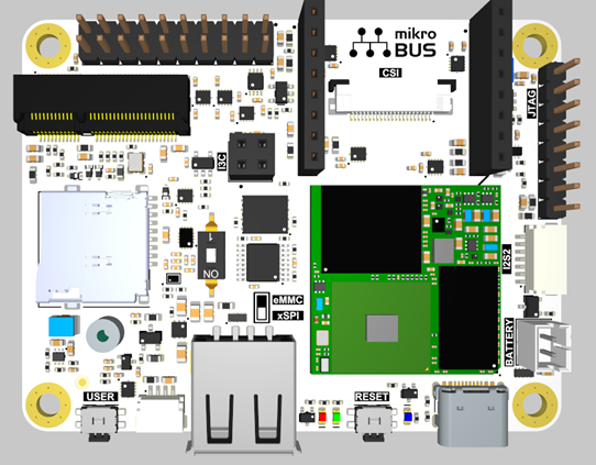
The Synaptics Coralboard is powered by the Synaptics Astra™ SL2619 Edge AI SoC that integrates the 1 TOPS Synaptics Torq™ inference engine featuring the industry's first implementation of Coral NPU. The board offers a rich set of hardware interfaces, including camera and display support using CSI/DSI and USB, microphone inputs, and Wi-Fi®/Bluetooth® connectivity through an M.2 expansion slot.
For help with any hardware, software, or other issues, please file a support request with Synaptics
Features:
- Synaptics Astra™ SL2619 SoC with Coral NPU
- 2GB DDR4 (optionally 1GB)
- MicroSD card slot for mass storage
- NOR flash memory
Additional features on Google I/O edition:
- mikroBUS hat board
- Arducam OV5647 1080p Mini Camera Module
I/O:
All I/Os are 3.3V except for the I2S2/I2S3 and I3C which are 1.8V.
- USB-C for power (5V only, no power negotiations) and data (device mode)
- USB-A host
- Battery – no charging functionality
- CSI (Camera Serial Interface) MIPI 2-lane connector – 22-pin, 0.5mm pitch
- DSI (Digital Serial Interface) MIPI 4-lane display interface
- I2S2 audio IO – stereo digital audio I/O using the standard I²S (Inter-IC Sound) protocol
- I2S3 audio IO
- I3C connector
- Qwiic Connect System for I2C
- mikroBUS connector
- GPIO header (2 x 10 male pin header, 2.54mm pitch)
- M.2 E-key or E+A key (SDIO 3.0, UART/PCM, and GPIOs)
- Debug interface – UART for kernel msg., etc. (see GPIO header below)
- Three LEDs – power and 2 user (1 default heartbeat)
- JTAG interface, THT holes for use with POGO-pin probe clip
- Two buttons (reset and user), 90-degree angled
- No power button
- Reset button is USB boot during reset
Additional functionality:
- All TPs are located on the underside of the board.
- Shunt resistors and related TPs (for power measurements of various functions) are accessible by pogo-pins from add-on board.
- All user connectors are located on one side of the board, for ease of enclosure integration.
Block diagram
See this PDF file for a block diagram of the main SL2619 SoM (System-on-Module) interface.
GPIO header definition
- 5V is either a source (if powered from USB-C) or can be used to power the board from an external 5V source.
- I/Os must be 3.3V.
I/O functions on 20-pin connector
| Pin | Function | Pin | Function |
|---|---|---|---|
| 1 | 3V3 | 2 | 5V0 |
| 3 | SM_TW0_SDA | 4 | GND |
| 5 | SM_TW0_SCL | 6 (output-only) | SM_URT0_TXD |
| 7 | SM_PWM2 | 8 (input-only) | SM_URT0_RXD |
| 9 | SM_GPIO27 | 10 | SM_ADCI5 |
| 11 | GPIO45 | 12 | GPIO42 |
| 13 | SM_SPI1_SDO | 14 | SM_SPI1_SS3n |
| 15 | SM_SPI1_SDI | 16 | 1V8 |
| 17 | SM_SPI1_CLK | 18 | SM_URT3_RXD |
| 19 | GPIO56 | 20 | SM_URT3_TXD |
Pins 6 (SM_URT0_TXD) and 8 (SM_URT0_RXD) are Linux CLI UART pins.
mikroBUS connector
- Follows the standard mikroBUS pin definition.
- 3.3V I/O.
- SM_ADCI3 is a dedicated analog input and cannot be used as GPIO.
- Address 0x60 is taken at SM_TW1.
- PMIC is connected to SM_TW1 and so these pins can be used only in I2C mode.
I/O functions on mikroBUS connector
| J6 Pin | Function | J7 Pin | Function |
|---|---|---|---|
| 1 | SM_ADCI3 (analog input only) | 1 | SM_PWM3 |
| 2 | GPIO47 | 2 | GPIO44 |
| 3 | SPI5_SS2n | 3 | URT5_RXD |
| 4 | SPI5_SCLK | 4 | URT5_TXD |
| 5 | SPI5_SDI | 5 | SM_TW1_SCL |
| 6 | SPI5_SDO | 6 | SM_TW1_SDA |
| 7 | 3V3 | 7 | 5V |
| 8 | GND | 8 | GND |
Other I/O connectors
I3C (J9) connector (1.8V)
| Pin | Function |
|---|---|
| 1 | SM_I3C_MS_SCA |
| 2 | 1V8 |
| 3 | SM_I3C_MS_SDL |
| 4 | GND |
Qwiic Connect for I2C (J8)
| Pin | Function |
|---|---|
| 1 | TW2_SCL |
| 2 | TW2_SDA |
| 3 | 3V3 |
| 4 | GND |
I2S2 (J4) connector (1.8V)
| Pin | Function |
|---|---|
| 1 | GND |
| 2 | I2S2_BCLK |
| 3 | I2S2_LRCK |
| 4 | I2S2_DO |
| 5 | I2S2_DI |
| 6 | I2S2_MCLK |
| 7 | 1V8 |
I2S3 (1.8V) - shared with M.2 connector
| Pin | Function |
|---|---|
| 1 | GND |
| 2 | I2S3_BCLK |
| 3 | I2S3_LRCK |
| 4 | I2S3_DO |
| 5 | I2S3_DI |
| 6 | NC (no connect) |
| 7 | 1V8 |
SL2619 datasheet
You can download the Synaptics SL261X processor datasheet directly from Synaptics.
Board software
The Synaptics Coralboard runs the Yocto Linux operating system.
The board software kit is based on the Synaptics Astra SDK but requires a corresponding board-specific BSP and preboot binaries in order to compile for this board. The software kit includes open-source software built on Yocto.
The Synaptics Linux Board Support Package (BSP) provides essential software, firmware, and drivers to boot and operate the Synaptics Coral Development Board SL. The BSP acts as the interface between the board's Yocto operating system and its specific hardware. It includes the necessary bootloaders, kernel drivers, and configuration files to ensure that the hardware functions correctly with the software.
When it comes to developing AI/ML applications to run on the board, you will use the Synaptics MLIR-based Torq™ compiler and runtime tools. You can find more information about developing AI/ML applications on the SL2619 and Coral NPU here.
The Torq™ open-source toolchain supports popular machine learning frameworks and models, enabling a unified development experience from model optimization to deployment. When coupled with Gemma, Google's open-source model family for the edge, the combined hardware and software stack offers a powerful, open foundation for building private and efficient edge AI applications.
Technical notes
SM_SPI1_SDO at the 20-pin connector (J5.13) should be in high-impedance state during CPU reset. This pin is BOOT_SRC1 and if driven externally it will affect boot mode of the device. Your actual result will depend on pin state and expected boot mode.
GPIO26 should be low during reset, but it is pulled up by a level shifter. No negative impact has been observed for this pin being high in u-boot and Linux setting. If you do encounter problems, however, then GPIO26 (Mikrobus J7.4) should be tied to GND during reset.